Edit Disk Bay Layout
To create a new layout using the wizard click . This will launch the Layout Wizard.
New Layout Wizard
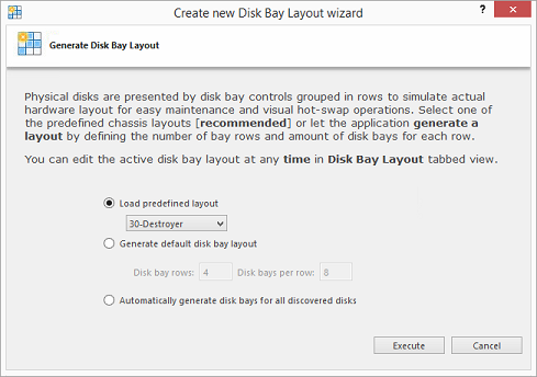
This configuration of a new layout can be done in one of three ways:
- Load predefined layout
- Here you can find one of our predefined layouts that may fit your system. If an appropriate layout is not listed you may try the next option.
- Generate default Disk Bay layout
- Define your hardware in terms of a disk array arranged in a X (columns) by Y (rows) grid of disks. You may make adjustments to
this later so this may just be a template to start from. Table-style layout will be created. The result for 2 columns and 5
rows could be looking as the following:
Figure 2: Grid Layout in Disk Bays View 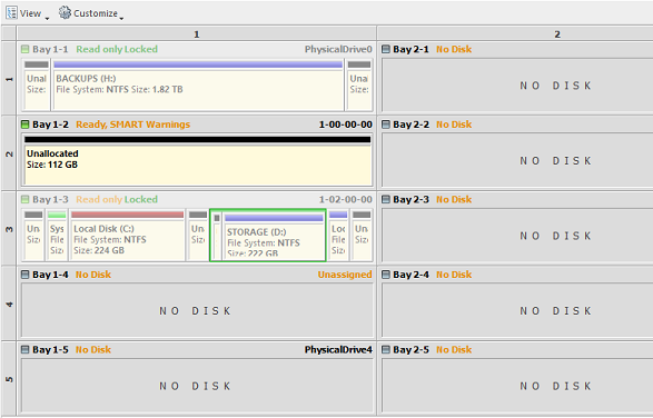
- Automatically generate Disk Bays for all available physical ports
- Defines your Disk Bay Layout based on the disks recognized by your system's Device Manager. The disks will be placed in their
own individual row when the layout is generated. The result could be looking as the following:
Figure 3: Auto-generated Layout 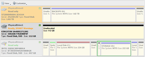
Select desired option and click Create button to create a default Disk Bay Layout.
Edit Existing Layout
To edit existing Disk Bay Layout select in the menu or use a shortcut .
This will bring you to the Disk Bays Layout View where you can manipulate, save, import and create Disk Bay Layouts.
- Free Grid Layout allows user to place Disk Bay widget at any position, change Bay widget size and its alignment (vertically or horizontally) individually for each Bay. Hence, user can create relatively accurate mocking layout of actual (physical) disk Bay slots located on hardware chassis.
- Table Layout is similar to Disk Bay Layout from previous versions. However, now user can re-size or select Disk Bay widgets by using row and column headers.
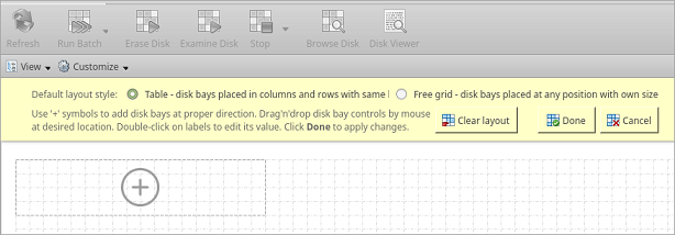
Create a New Layout
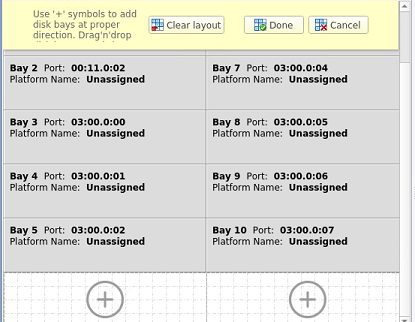
To create a new Disk Bay Layout select either Free Grid or Table layout option and start adding Disk Bays using circled (+) symbols.
If predefined layout already exists click Clear Layout to remove it and create a new one.
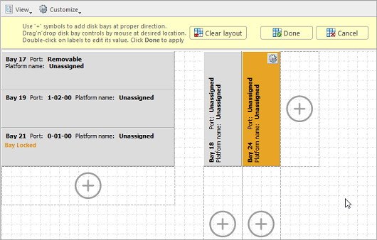
Layout Editing Tips
- Click on circled (+) signs to add new Disk Bay widget on a side of existing one. New Disk Bay widget size will be corresponded to adjusted Disk Bay.
- To re-size Disk Bay use mouse to drag it's right side or bottom.
- To set Disk Bay vertically-oriented use mouse to drag it's right side to shrink it until it changes to vertical state.
- To delete Disk Bay select it and press Delete keyboard key or use service menu by clicking “gear” sign on left upper corner.
- Use mouse to drag-n-drop selected Disk Bay widgets to new location. If hovered location is invalid Disk Bay widgets will be highlighted with crossed sign.
- To change disk label or port, click on corresponded labels on disk widget to start editing.
- To change Disk Bay attributes use menu by clicking on “gear” sign on selected Bay.
Due to different hard disk controller manufacture standards and platform limitations physical disk port address format may vary.
If both platform name and disk port are assigned to Disk Bay widget then platform name is used for Disk Bay mapping.
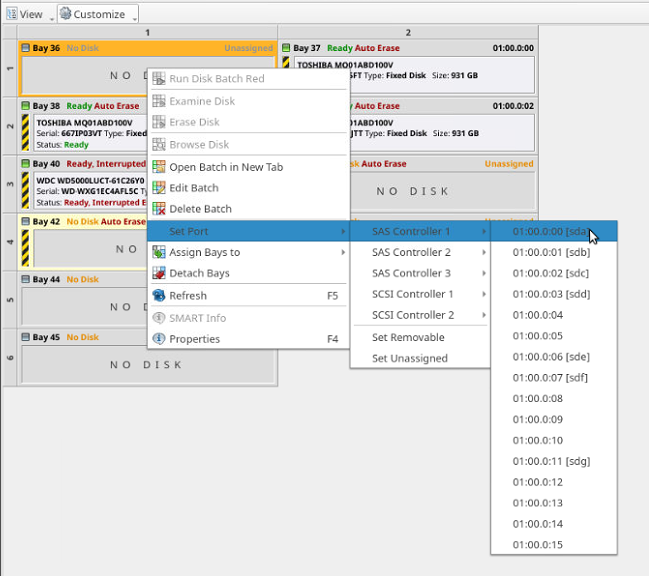
Mapping Ports to Bays
- Choose one of the disk bays you want to map
- Take a physical HDD/SSD and plug it into that bay
- Right-click on the corresponding bay in KillDisk Industrial
- Select the proper controller, then click on the port from the drop-down that shows a drive connected to it (look for a new name like “/sda”)
- Repeat for all the rest of the bays, plugging disks and mapping one at a time.
For some type of controllers static ports cannot be determined when new device appears, thus these disks cannot be statically linked to particular bays, for example, this happens for removable USB Disks which may have the same port number when inserted in different physical USB slots.
If you want to map a particular bay on the layout to be linked with a newly inserted disk which port is dynamically determined, from disk bay's context menu click then click type of disk you want to appear: Removable or Fixed.
Saving and Reverting Changes
Done will apply current change to the application session so the changes will be seen in the Disk Bays view and even be loaded in future application launch. These changes will not affect the .dbl file.
Click Cancel to revert any changes you made to the layout.
Make sure to save the layout by clicking Done otherwise your layout will be lost.